Job preferences

Utku Olcar
is open to work
Job titles
Robotics Engineer · Robotics Software Engineer · Robotics Specialist · Mechatronics Engineer · Embedded Software Engineer
Start date
Immediately, I’m actively applying
Job types
Full-time (I can work remotely)
If you are hiring, leave an email address, please.
Whole Body Teleoperation of Humanoid Robot
Details
- Date : November 3, 2017
- Category : Robotic Calculations
- Organization : BAU Robotics Lab
SUMMARY
In this project, the main idea is that driving a humanoid robot with a human body as a remote control while keeping it in balance.
Using the skeletal tracking function of Microsoft Kinect Sensor, the three-dimensional position information of human body joints are taken. These positions are converted to the necessary joint angles of the humanoid robot. Using forward kinematics, the center of mass positions of all links are calculated with respect to the robot frame, in the light of the forward kinematics and center of mass of the humanoid robot is computed. The balancing algorithm is applied to the humanoid robot’s leg servo motor angles to keep the robot in balance. Finally, the program sends the angles to the robot via Bluetooth connection and set all the sixteen joint angles.
In addition, you can find another application of this project also developed by me for entertainment and marketing purpose : Aygaz Brandweek
INTRODUCTION
One of the most important titles about robotic researches is humanoid robotics. Some scientists and industrialists prefer to develop robots humanlike, because of two main reasons. One of them is that experimentally if you want to create a robot that is working for people and do some works that people do, the easiest and guaranteed way to decide a robotic design to produce is a humanlike robot design.
The second reason is that people like robots that have a human-like shape. If it is wanted to market and sell a product, it needs to make it in such a way that people like it.
Humanoid robots are designed to be similar to human anatomy so they do almost the same movements to do the same job as ordinary people. Due to this similarity, people could control a humanoid robot using their own body as a remote control and teach movements to the robot with a teleoperation system and this teleoperation system should be robust and easily practicable.
The main problem with these whole body teleoperation systems is kept in balance the humanoid robot. Humanoid robots usually have 2 legs like humans and this design has a difficult challenge for developers. Humanoid robots have to be self-balanced in such a way.
1.1 SKELETAL TRACKING
Skeletal Tracking allows Kinect to recognize people and follow their actions. Using the infrared (IR) camera, Kinect can recognize up to six users in the field of view of the sensor. Of these, up to two users can be tracked in detail. An application can locate the joints of the tracked users in space and track their movements over time.
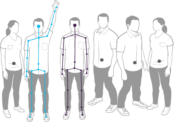
Figure 1 Kinect can recognize six people and track two
Skeletal Tracking is optimized to recognize users standing or sitting, and facing the Kinect; sideways poses provide some challenges regarding the part of the user that is not visible to the sensor. To be recognized, users simply need to be in front of the sensor, making sure the sensor can see their head and upper body; no specific pose or calibration action needs to be taken for a user to be tracked.
1.2 FORWARD KINEMATICS
Kinematics is the science of motion that treats motion without regard to the forces which cause it. Within the science of kinematics, one studies position, velocity, acceleration, and all higher order derivatives of the position variables (with respect to time or any other variable(s)). Hence, the study of the kinematics of manipulators refers to all the geometrical and time-based properties of the motion. Manipulators consist of nearly rigid links, which are connected by joints that allow relative motion of neighboring links. These joints are usually instrumented with position sensors, which allow the relative position of neighboring links to be measured. In the case of rotary or revolute joints, these displacements are called joint angles. Some manipulators contain sliding (or prismatic) joints, in which the relative displacement between links is a translation, sometimes called the joint offset.
The number of degrees of freedom that a manipulator possesses is the number of independent position variables that would have to be specified in order to locate all parts of the mechanism. This is a general term used for any mechanism. For example, a four-bar linkage has only one degree of freedom (even though there are three moving members). In the case of typical industrial robots, because a manipulator is usually an open kinematic chain, and because each joint position is usually defined with a single variable, the number of joints equals the number of degrees of freedom. At the free end of the chain of links that make up the manipulator is the end effector. Depending on the intended application of the robot, the end-effector could be a gripper, a welding torch, an electromagnet, or another device. We generally describe the position of the manipulator by giving a description of the tool frame, which is attached to the end-effector, relative to the base frame, which is attached to the nonmoving base of the manipulator.
A very basic problem in the study of mechanical manipulation is called forward kinematics. This is the static geometrical problem of computing the position and orientation of the end-effector of the manipulator. Specifically, given a set of joint angles, the forward kinematic problem is to compute the position and orientation of the tool frame relative to the base frame. Sometimes, we think of this as changing the representation of manipulator position from a joint space description into a Cartesian space description.
1.3 DENAVIT – HARTENBERG (D-H) CONVENTION
A commonly used convention for selecting frames of reference in a robotic application is Denavit - Hartenberg convention. In this convention, the position and orientation of the end-effector is given by
H =T{0 \atop n} = T{1 \atop 0} T{2 \atop 1} T{3 \atop 2} ... T{n \atop n-1}
Where,
T{i \atop i-1} = \begin{bmatrix} R{i \atop i-1} & o{i \atop i-1}
\\[1em] 0 & 1 \end{bmatrix}
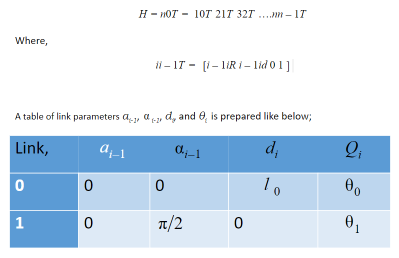
Table 1-1 Denavit-Hartenberg Convention Table :
- ai−1 = the distance from zi−1 to zi measured along xi−1
- αi−1 = the angle between zi−1 to zi measured about xi−1
- di is the distance from xi−1 to xi measured along zi
- θi is the angle between xi−1 to xi measured about zi
Transform matrix can be written in following form:
T{i \atop i-1} = \begin{bmatrix} \cos\theta{ \atop i} & -\sin\theta{ \atop i}\cos\alpha{ \atop i-1} & \sin\theta{ \atop i}\sin\alpha{ \atop i-1} & a{ \atop i-1}\cos\theta{ \atop i} \\[1em] \sin\theta{ \atop i} & \cos\theta{ \atop i}\cos\alpha{ \atop i-1} & -\cos\theta{ \atop i}\sin\alpha{ \atop i-1} & a{ \atop i-1}\sin\theta{ \atop i} \\[1em] 0 & \sin\alpha{ \atop i-1} & \cos\alpha{ \atop i-1} & d{ \atop i} \\[1em] 0 & 0 & 0 & 1 \\[1em] \end{bmatrix}
Figure 2 Transform Matrix from Denavit-Hartenberg Table
You can find the explanation of the D-H algorithm in the Appendices part.
PROJECT DESCRIPTION & ARCHITECTURE
In this project, the main purpose is to operate a humanoid robot with a human body as a remote control. If human body skeleton angles could be tracked by the software, it is easily convertible to the humanoid robot joint angles.
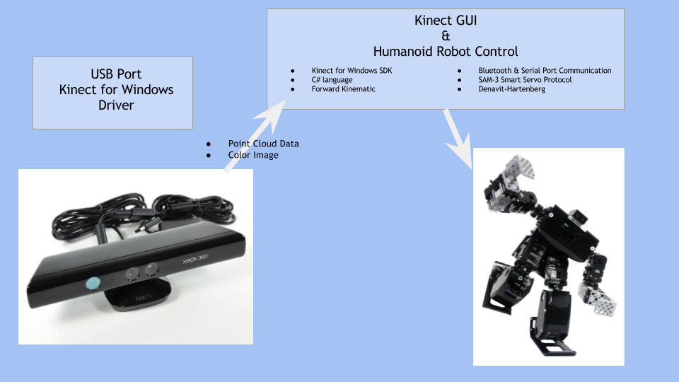
Figure 3 Flow Chart
2.1 GET SKELETON JOINT ANGLES DATA
Microsoft Kinect Sensor was used to get human joint data. Kinect gives you the 3-dimensional positions of joints with respect to the Kinect Sensor frame. The joints that Kinect gives you has been shown in figure 3;
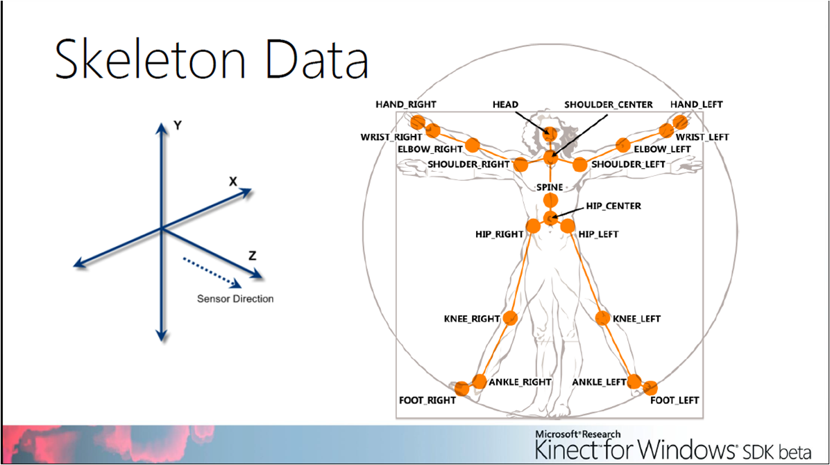
Figure 4 Kinect Sensor – Skeleton Data (Version 1)
Human axis frame is calculated by the software as, the origin point of the axis frame is the middle point of “HIP_RIGHT” and “HIP_LEFT” point,
- Z-axis is the direction of the “SHOULDER_CENTER” point.
- Y-axis is the direction of the “HIP_LEFT” point.
- X-axis is the cross product of the Y axis and the Z-Axis.
Whole the sixteen desired joint angles were calculated one by one from the skeleton frame of Kinect Sensor.
2.2 ROBOT BALANCING
While the code is running and the humanoid robot joints are moving, we need to know where is the mass of the center of this humanoid robot to keep it in balance.
Humanoid robot main axis frames are specified as shown in figure 3;
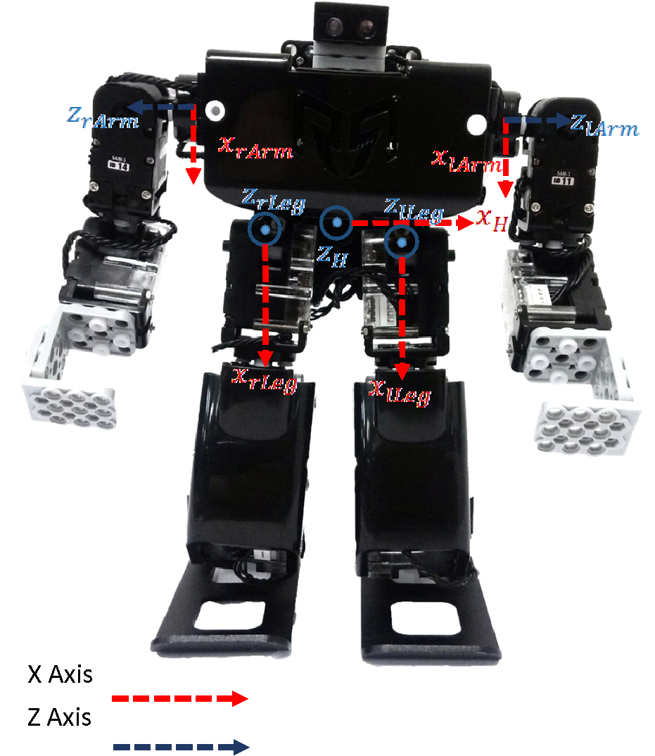
Figure 5 Robobuilder RQ-Huno Humanoid Robot – Specified Axis Frames
Calculated transform matrixes with respect to the base axis frame are shown below (distance unit is millimeter);
T{Huno \atop Left Leg} =\begin{bmatrix} 0 & -1 & 0 & 20mm \\[1em] 1 & 0 & 0 & 0 \\[1em] 0 & 0 & 1 & 0 \\[1em] 0 & 0 & 0 & 1 \\[1em] \end{bmatrix}
T{Huno \atop Right Leg} = \begin{bmatrix} 0 & -1 & 0 & -20mm \\[1em] 1 & 0 & 0 & 0 \\[1em] 0 & 0 & 1 & 0 \\[1em] 0 & 0 & 0 & 1 \\[1em] \end{bmatrix}
T{Huno \atop Left Arm} = \begin{bmatrix} 0 & -1 & 0 & 30mm \\[1em] 0 & 0 & -1 & 40mm \\[1em] 1 & 0 & 0 & 35mm \\[1em] 0 & 0 & 0 & 1 \\[1em] \end{bmatrix}
T{Huno \atop Left Arm} = \begin{bmatrix} 0 & -1 & 0 & -30mm \\[1em] 0 & 0 & 1 & 40mm \\[1em] -1 & 0 & 0 & 35mm \\[1em] 0 & 0 & 0 & 1 \\[1em] \end{bmatrix}
Figure 6 Transform Matrixes of Specified Axis Frames
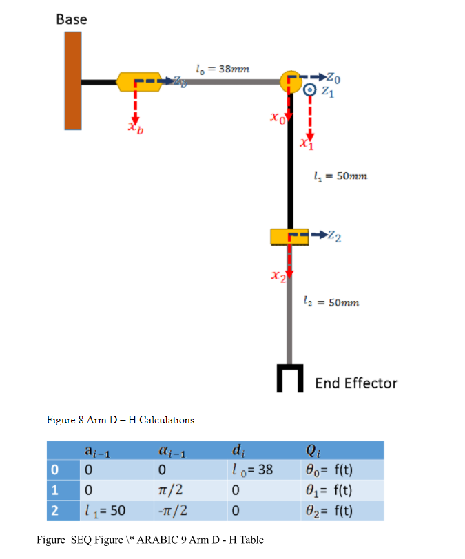
You can find the implemented D-H algorithm for all joints of a humanoid robot one by one. D-H tables are shown below of the figures so transform matrixes of the whole body could be calculated in the light of the figures and the order between the joints. Before, it is clarified how to write a transform matrix from a D-H table.
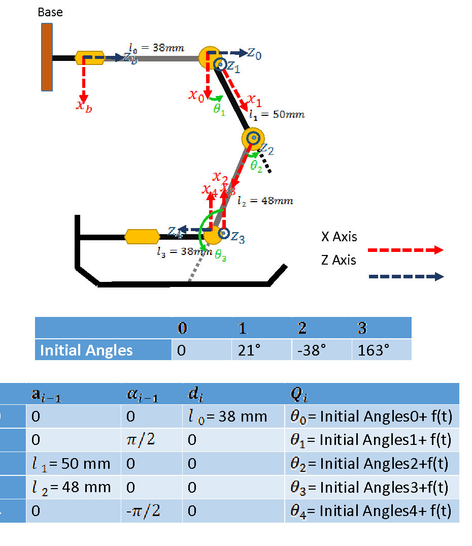
Figure 7 Leg D-H Table
2.2.1 MEASUREMENTS
Some measurements have to be done to calculate the center of mass of the humanoid robot. The forward kinematics for every joint has been calculated already. This means if the three-dimensional position of a point is known with respect to one joint axis frame, this point’s three-dimensional position with respect to the robot base axis frame is easily computable.
Link measurements are shown below;
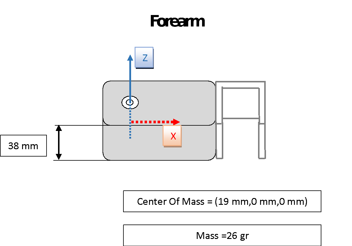 Figure 10 Forearm Measurements
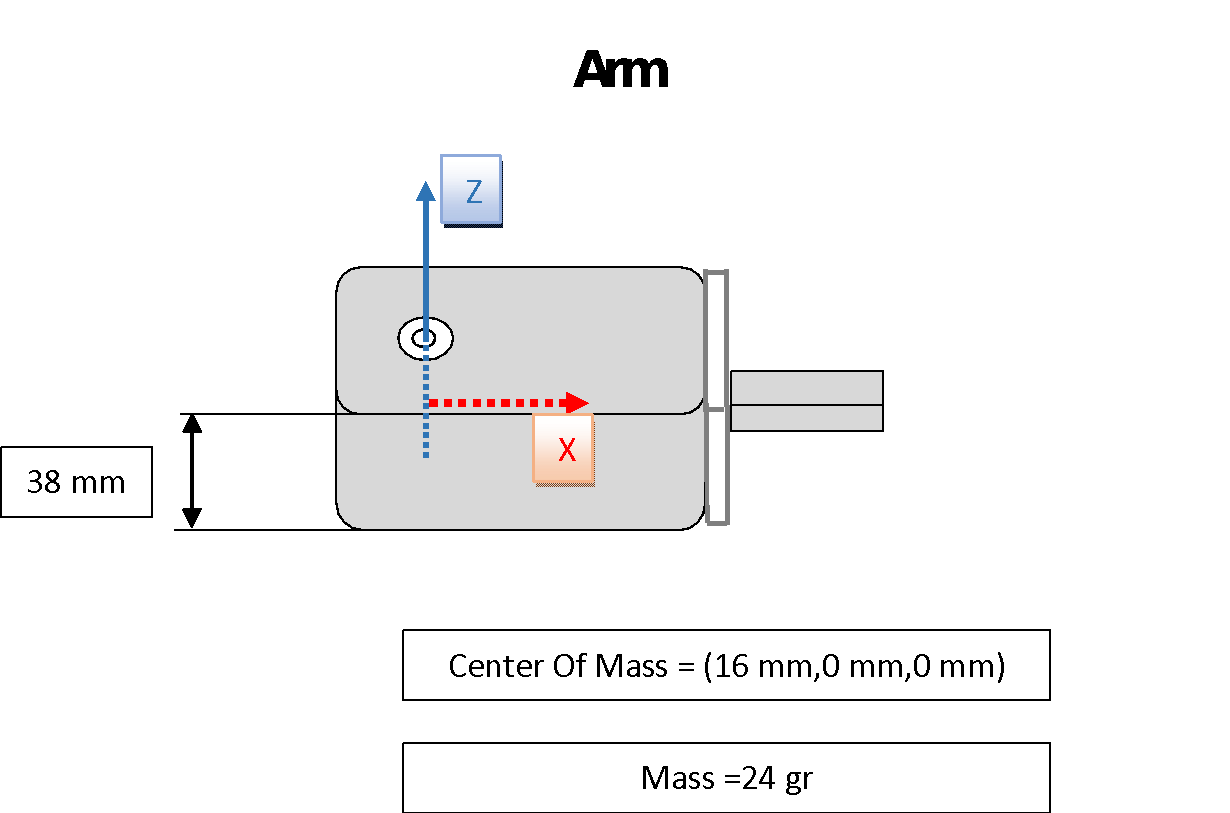 Figure 11 Arm Measurements
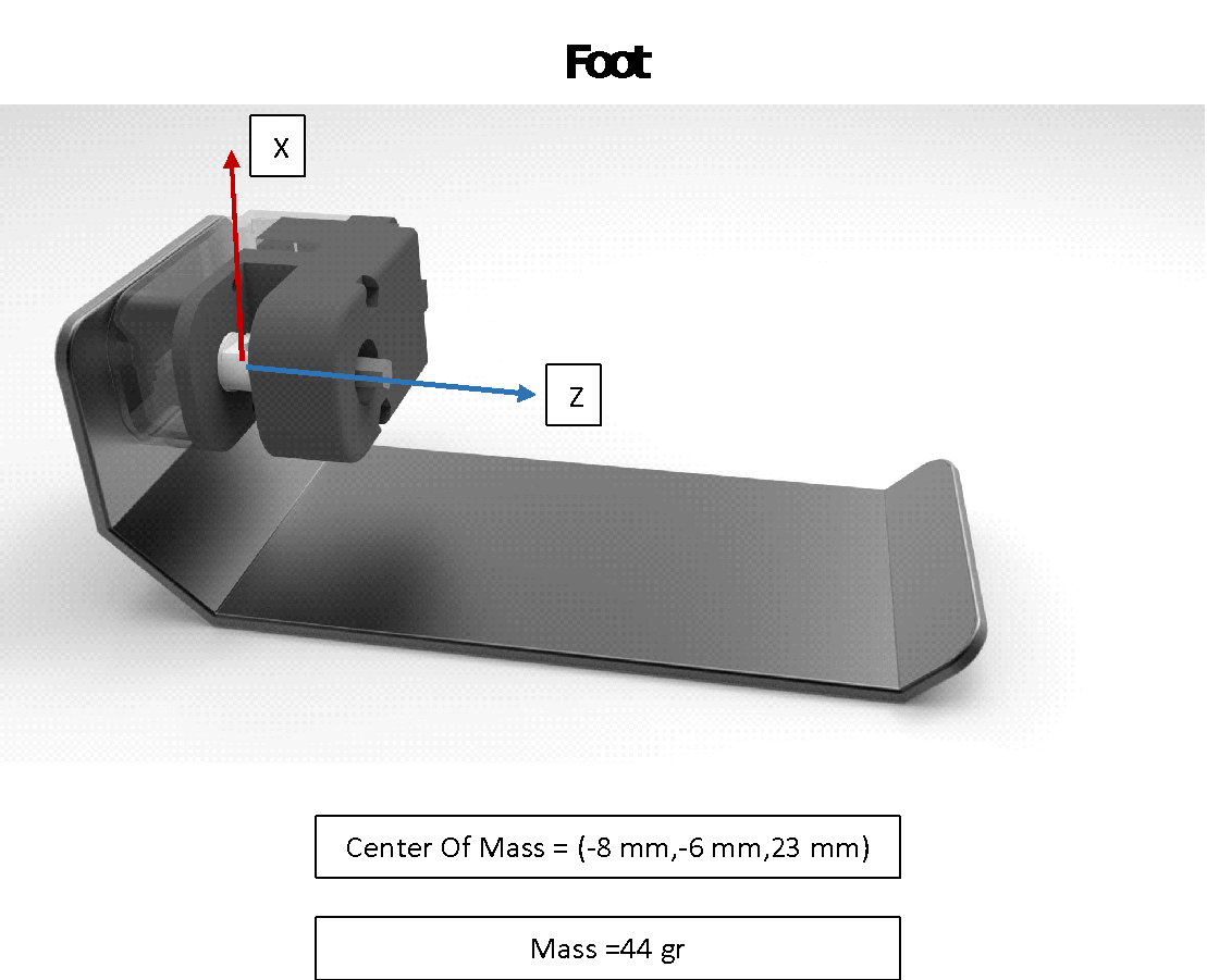 Figure 12 Foot Measurements
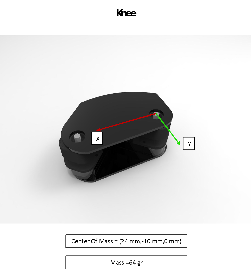 Figure 13 Knee Measurements
After all these forward kinematics, D-H tables, and the calculations, it is known where is exactly the center of mass point with respect to huno base axis frame,
2.2.2 BALANCE ALGORITHM
In this project, one of the important parts is to keep the robot in balance, so basically, program detects which feet (or both) contact with the ground and tries to keep the center of mass point inside the area of the contacting sole plane. The figure shown below explains the principle;
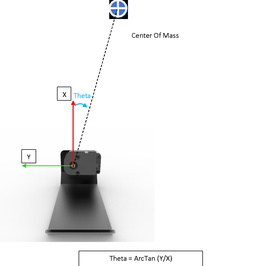 Figure 14 Balance Algorithm
If the transform matrix of the last joint was calculated when the angle was zero (0), this arc sinus calculation gives the desired angle to keep it in balance.
Multiplication between the inverse of ankle joint transform matrix and the center of mass position WRT base gives the center of mass position WRT ankle joint. ‘X’ and ‘Y’ are the position variables of the center of mass position WRT ankle joint.
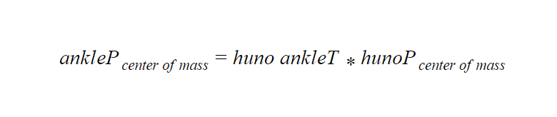 Equation 1 Center of Mass WRT Ankle Axis Frame
2.3 DRIVING ROBOT SERVO MOTORS
RQ-Huno humanoid robots made from the assembly of Robobuilder SAM-3 Smart Servo Motors and this type of servo motors have their own communication protocol. For example, to activate the “Position Move” function, you need to send a four-byte data packet;
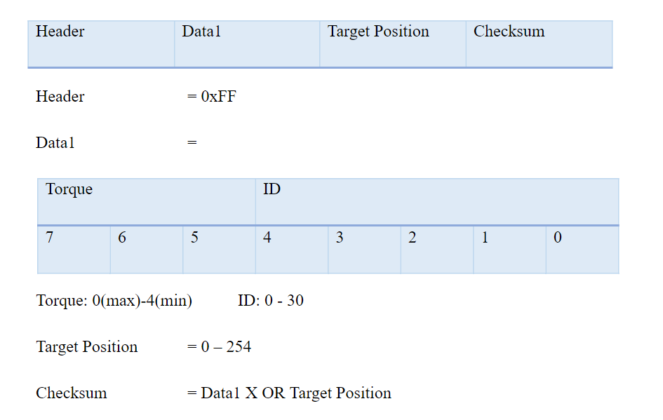
This Target position is not the angle of the servo motor! In this project, the robot is programmed to use “Standard Resolution” as shown in the figure. The conversation from the angle in the degree to the target position of SAM-3 Servo Motor for “Standard Resolution” is a mapping function from (0 - 269) to (0 – 254)
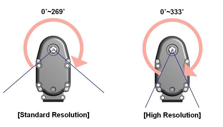 Figure 15 Resolution
In this case, the angles calculated as in the figure so the mapping function is easily from (0° – 134.5°) to (127 – 254)
Figure 15 Resolution
In this case, the angles calculated as in the figure so the mapping function is easily from (0° – 134.5°) to (127 – 254)
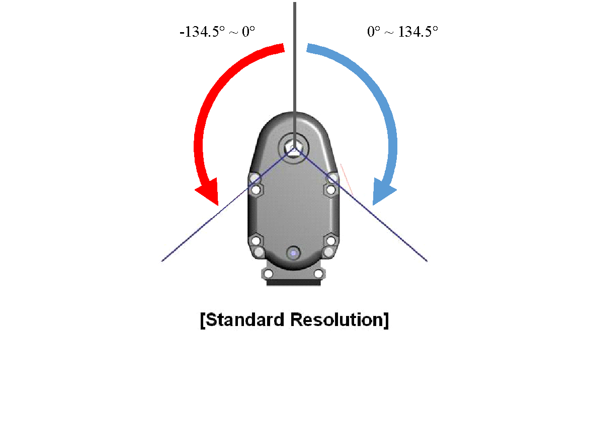 Figure 16 – SAM-3 Servo Angles in This Project
XOR Gate:
The XOR gate (sometimes EOR gate, or EXOR gate and pronounced as Exclusive OR gate) is a digital logic gate that gives a true (1/HIGH) output when the number of true inputs is odd. An XOR gate implements an exclusive or; that is, a true output result if one, and only one, of the inputs to the gate is true. If either input are false (0/LOW) or both are truly a false output results. XOR represents the inequality function, i.e., the output is true if the inputs are not alike otherwise the output is false. A way to remember XOR is "one or the other but not both".
Mapping Function
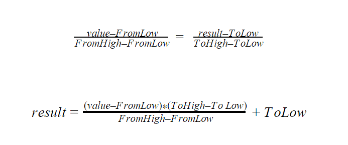 Equation 2 Mapping Function
SOFTWARE TOOLS
Microsoft Visual Studio 2015 was the main tool to program. Microsoft Kinect SDK was added to the project to program the Kinect Sensor.
3.1 MICROSOFT VISUAL STUDIO
Visual Studio is a complete set of development tools for building ASP.NET Web applications, XML Web Services, desktop applications, and mobile applications. Visual Basic, Visual C#, and Visual C++ all use the same integrated development environment (IDE), which enables tool sharing and eases the creation of mixed-language solutions. In addition, these languages use the functionality of the .NET Framework, which provides access to key technologies that simplify the development of ASP Web applications and XML Web Services.
Visual Studio includes a code editor supporting IntelliSense (the code completion component) as well as code refactoring. The integrated debugger works both as a source-level debugger and a machine-level debugger. Other built-in tools include a forms designer for building GUI applications, web designer, class designer, and database schema designer. It accepts plug-ins that enhance the functionality at almost every level—including adding support for source-control systems (like Subversion) and adding new toolsets like editors and visual designers for domain-specific languages or toolsets for other aspects of the software development lifecycle (like the Team Foundation Server client: Team Explorer).
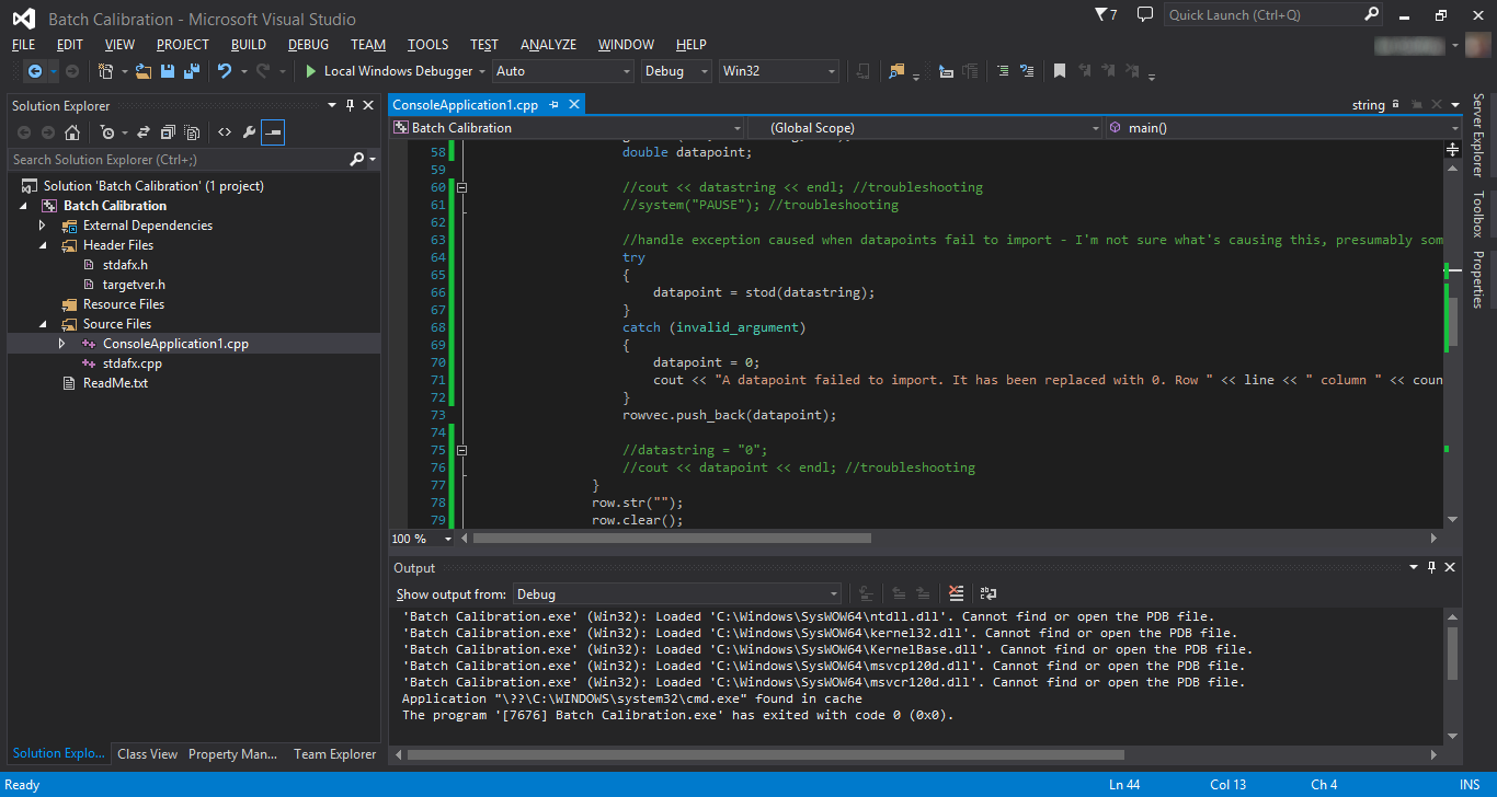 Figure 17 Visual Studio IDE
3.2 MICROSOFT KINECT SDK
The Kinect for Windows Software Development Kit (SDK) enables developers to create applications that support gesture and voice recognition, using Kinect Sensor technology on computers running Windows.
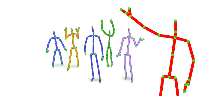 Figure 18 Kinect Skeletons
3.3 SOLID GEOMETRY C# LIBRARY
Solid geometry library is an open-source C# library to compute some basic linear algebra calculations, especially for kinematic operations. You could instantiate vectors, rotational matrixes, and transform matrixes and use some sort of functions. This library is accessible on the link in references.
3.4 ROBOBUILDER TOOLS
Action Builder and Motion Builder softwares are developed by Robobuilder Company to program their robots. Using Motion Builder, you can create a script to upload the robot without coding. This script has the information of which servo motor will be set predefined position at a certain time. Action Builder software also creates scripts but the difference is that Action Builder Scripts specify when will be the Motion Builder Scripts triggered depending on the sensors or depending on the time. These softwares were used to understand how the RQ-Huno humanoid robot works and what the initial servo positions of humanoid robot are.
HARDWARE TOOLS
4.1 MICROSOFT KINECT SENSOR
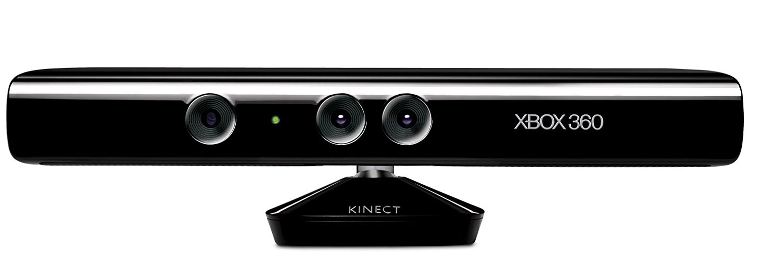
Kinect (codenamed Project Natal during development) is a line of motion sensing input device by Microsoft for Xbox 360 and Xbox One video game consoles and Windows PCs. Based around a webcam-style add-on peripheral, it enables users to control and interact with their console/computer without the need for a game controller, through a natural user interface using gestures and spoken commands. The first-generation Kinect was first introduced in November 2010 in an attempt to broaden Xbox 360's audience beyond its typical gamer base. A version for Windows was released on February 1, 2012. Kinect competes with several motion controllers on other home consoles, such as Wii Remote Plus for Wii and Wii U, PlayStation Move/PlayStation Eye for PlayStation 3, and PlayStation Camera for PlayStation 4.
Microsoft released the first Beta of the Kinect software development kit for Windows 7 on June 16, 2011. This SDK was meant to allow developers to write Kinecting apps in C++/CLI, C#, or Visual Basic .NET.
4.2 RQ-HUNO HUMANOID ROBOT
The RQ-HUNO Robotic Humanoid Kit is a new robotic DIY kit designed to provide robot enthusiasts with the value of Education and Entertainment and an affordable, feature-rich level Humanoid Robot. It includes all the latest technology available in higher-end Humanoids (16 DoF, Daisy Chain Serial bus, Obstacle, and Sound Detection Sensors, USB connectivity, and Android Remote Control app*) while being an affordable Humanoid Platform.
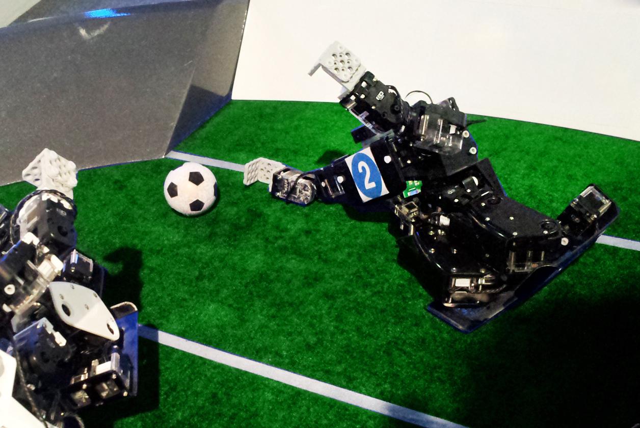 Figure 19 RQ-Huno Football Player
Design Various Robots
Design and build various robots simply by plugging together block-type robotic actuator modules. Without programming, users can download robotic motion files from the internet and play them on the RQ platforms.
 Figure 20 RQ-Huno Custom Assembly
Microsoft Robotics Studio
RQ-HUNO is compatible with the new Microsoft Robotics Studio 4 and the Powerful MSRDS Visual Programming Language. This lets you design advanced Robot behaviors with a simple, flowchart style programming environment.
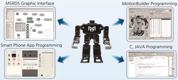 Figure 21 RQ-Huno GUI Development Tools
FEATURES
SAM-3 Exclusive Actuators The exclusive SAM-3 Robot Actuators offer a torque of 3kgf.cm and an impressive speed. This makes the lightweight RQ-HUNO very quick and agile.
Joint Assembly System for Simple and Reliable Assembly RQ-HUNO's unique Joint Assembly system makes assembling the Robot a breeze. The Robot is assembled using a combination of Joints, Rivets, and screws.
Wireless Remote Control RQ-HUNO includes an Infrared Remote for Wireless Remote control. When the Robot is equipped with the Bluetooth Module (optional and not included), it can be wirelessly controlled with your Android Device.
32-bit Micro Controller with Sound and Obstacle Detection Sensors RQ-HUNO comes with an ARM Cortex M3 microcontroller. The controller is capable of storing up to 21 motions (11 pre-defined + 10 user-defined) and up 10 Autonomous Behaviors.
SAM-3 SMART SERVO MOTOR
The Robobuilder SAM-3 Smart Serial Servo Motor is the smallest servo is the Robobuilder SAM Series. This servo is the heart of the RQ-HUNO Humanoid Robot. Measuring 36mm x 27.6mm x 20mm, SAM-3 offers 3kgf.cm torque and uses a rich Daisy Chain Serial protocol.
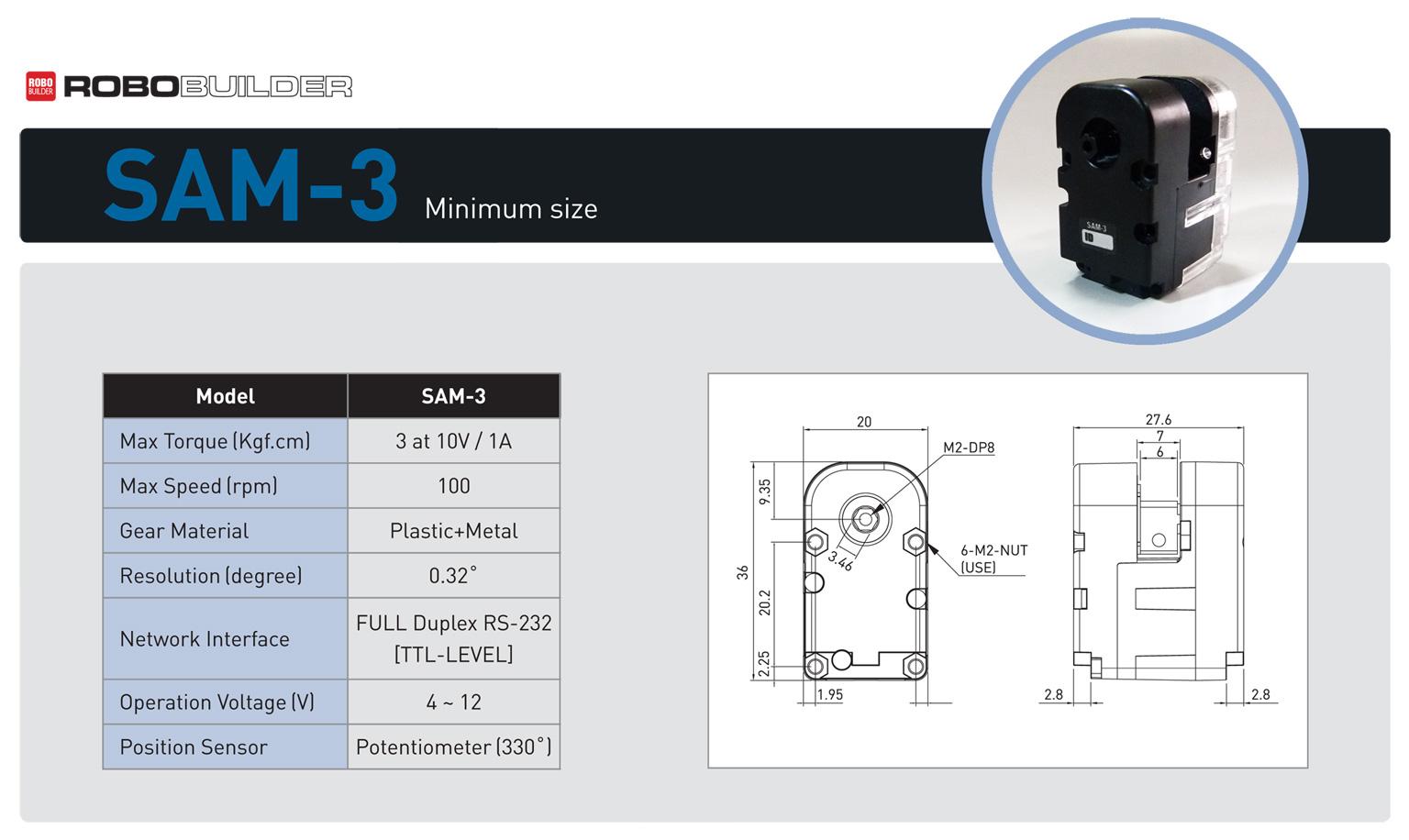 Figure 22 SAM-3 Smart Servo Motor
The Robobuilder SAM-3 Smart Serial Servo Motor uses the same wCk protocol used in the 5710K/5720T Robots making it compatible with the 57xx series Robots. In addition, the TTL serial interface enables compatibility with Arduino, PIC and any many other MCUs (see the Resources Section below for samples about using SAM-3 with Arduino).
Full-duplex UART (TTL level) for serial control
Daisy chain system (each servo has its own unique ID)
Position control mode or wheel mode (continuous rotation) with speed control
PID control
Main Protocol features:
- Position Set/Wheel mode with Real-time position feedback
- Adjustable PID gain
- Torque On/Off for "catch and play" and third state: Dynamic Brake (puts the servo in an intermediate holding state without using any energy)
- Control table with over 30 parameters (see the Resources below for full documentation)
4.3 DAISY CHAIN SERIAL PROTOCOL
Some hardware can be attached to a computing system in a daisy chain configuration by connecting each component to another similar component, rather than directly to the computing system that uses the component. Only the last component in the chain directly connects to the computing system. For example, chaining multiple components that each have a UART port to each other. The components must also behave cooperatively. e.g., only one seizes the communications bus at a time.
SCSI is an example of a digital system that is electrically a bus, in the case of external devices, is physically wired as a daisy chain. Since the network is electrically a bus, it must be terminated and this may be done either by plugging a terminator into the last device or selecting an option to make the device terminate internally.
MIDI devices are usually designed to be wired in a daisy chain. It is normal for a device to have both a THRU port and an OUT port and often both can be used for chaining. The THRU port transmits the information through with minimal delay and no alteration, while the OUT port sends a completely regenerated signal and may add, remove, or change messages, at the cost of some delay in doing so. The difference can result in the signals arriving at different times; if the chain is long enough, it will be distorted so much that the system can become unreliable or non-functional.
Some Serial Peripheral Interface Bus (SPI) IC products are designed with daisy chain capability.
4.4 WIRELESS COMMUNICATION
BLUETOOTH
A Bluetooth® device uses radio waves instead of wires or cables to connect to a phone or computer. A Bluetooth product, like a headset or watch, contains a tiny computer chip with a Bluetooth radio and software that makes it easy to connect. When two Bluetooth devices want to talk to each other, they need to pair. Communication between Bluetooth devices happens over short-range, ad hoc networks known as piconets. A piconet is a network of devices connected using Bluetooth technology. When a network is established, one device takes the role of the master while all the other devices act as slaves. Piconets are established dynamically and automatically as Bluetooth devices enter and leave radio proximity. If you want a more technical explanation, you can read the core specification or visit the Wikipedia page on Bluetooth for a deeper technical dive.
RQ-Huno Humanoid Robot has Bluegiga WT12 Bluetooth Class 2 Module.
Bluegiga WT12 Bluetooth Class 2 Module :
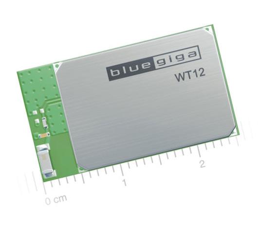
The WT12 is a fully integrated Bluetooth® 2.1 + EDR, class 2 module combining antenna, Bluetooth radio, and an on-board iWRAP Bluetooth stack. Bluegiga's WT12 constitutes the ideal solution for developers that want to quickly integrate Bluetooth wireless technology into their design without investing several months in Bluetooth radio and stack development. It uses Bluegiga's iWRAP Bluetooth stack, which is an embedded Bluetooth stack implementing 13 different Bluetooth profiles and Apple iAP connectivity. The WT12 combined with iWRAP Bluetooth stack and Bluegiga's excellent technical support designers ensure quick time-to-market and low development costs and risks.
PROBLEMS & SOLUTIONS
5.1 KINECT SENSOR SDK
In this project, the first version of Kinect Sensor has been used. Microsoft has released the second version of Kinect Sensor in 2013 and has published the “Kinect for Windows SDK 2.0” to use the new Kinect’s abilities efficiently on 10/21/2014. The latest version of SDK is only available for the newest Kinect Sensor, so it has not worked in this project. Also, the version “1.8” of SDK has been tried for the project but because of a bug in this version, it could not be used, unfortunately. Kinect for Windows 1.7 SDK has solved the problem and worked properly.
CONCLUSION
Teleoperation systems that imitate human movements and are controlled by a human body are infrequent projects and these workings are approved as best projects about robotics. According to this, driving a little humanoid robot with a human body as a remote control could be the first step to reach the goal of creating a humanoid robot that act like a human and has artificial intelligence.
Not only the science-fiction but also the modern industrial applications show us, the focus of robotics’ rapid progress is that the machines which take the human’s place and do, whatever the work is, indefatigably without harm. This project is a little practice of how we could move a load without any effort using a robot with our own body as a remote control.
This project looks like entertainment purposes, but with the bigger and powerful mechanical systems and more robust controls, it is not an imaginary thought to have robotic workers or soldiers controlled by real humans, in the future.
REFERENCES
- John J. Craig, 2005, “Introduction to Robotics Mechanics and Control Third Edition”
- “Skeletal Tracking”, https://msdn.microsoft.com/en-us/library/hh973074.aspx
- “Kinect for Windows SDK 2.0” ,https://www.microsoft.com/en-us/download/details.aspx?id=44561
- “XOR gate”, https://en.wikipedia.org/wiki/XOR_gate
- “What is Bluetooth?”https://www.bluetooth.com/what-is-bluetooth-technology/how-it-works
- “Bluegiga WT12 Bluetooth Class 2 Module”, https://www.silabs.com/products/wireless/bluetooth/bluetooth-classic-modules/Pages/wt12-bluetooth-class-2-module.aspx
- “SolidGeometry”,https://github.com/utkuolcar/SolidGeometry
- “Robobuilder Creator User’s Manual”
- “Robobuilder RQ-Huno User Manual”
- “RQ-HUNO Robotic Humanoid Kit”,http://www.robotshop.com/en/rq-huno-robotic-humanoid-kit.html
- “Computer hardware”, https://en.wikipedia.org/wiki/Daisy_chain_(electrical_engineering)
APPENDICES
ALGORITHM FOR MODIFIED D-H CONVENTION
Step - 1: Assigning of base frame: the base frame {0} is assigned to link 0. The base frame {0} is arbitrary. For simplicity chose z0 along the z1 axis when the first joint variable is zero. Using this convention, we have a0 = 0 andα0 = 0. This also ensures that d1 =0 if the joint is revolute and θ1 =0if the joint is prismatic.
Step - 2: Identify links. The link frames are named by number according to the link to which they are attached (i.e. frame is attached rigidly to link i). For example, the frame {2} is attached to link 2.
Identify joints. The z-axis of frame , called zi , is coincident with the joint axis i. The link i has two joint axes, zi and zi+1. The zi axis is assigned to joint i and zi+1is assigned to joint (i+1).
For i = 1,….., n perform steps 3 to 6.
Step – 3: Identify the common normal between zi and zi+1 axes, or point of intersection. The origin of frame is located where the common normal (ai ) meets the zi axis.
Step – 4: Assign the zi axis pointing along the ith joint axis.
Step – 5: Assign xi axis pointing along the common normal (ai ) in the
direction from zi axis to zi+1axis. In the case of ai = 0, xi is normal to the plane of zi and zi+1axes.
As seen in figure 3.7, the joints may not necessarily be parallel or intersecting. As a result, the z-axes are skew lines. There is always one line mutually perpendicular to any two skew lines, called the common normal, which has the shortest distance between them. We always assign the x-axis of the local reference frames in the direction of the common normal. Thus, if ai represents the common normal between zi and zi+1, the direction xi is along ai.
If two joint z-axes are parallel, there are an infinite number of common normals present. We will pick the common normal that is collinear with the common normal of the previous joint.
If the z-axes of two successive joints are intersecting, there is no common normal between them (or it has zero length). We will assign the x-axis along a line perpendicular to the plane formed by the two axes.
Step – 6: The yi axis is selected to complete the right-hand coordinate system.
Step – 7: Assigning of end-effector frame: If the joint n is revolute, the direction of xn is chosen along the direction of xn−1 when θn = 0 and the origin of frame is chosen so that dn = 0 . If the joint n is prismatic, the direction of xn is chosen so that θn = 0and the origin of frame is chosen at the intersection of xn−1with zn so that dn = 0 .
Step – 8: The link parameters are determined as mentioned in table 4.
Table 4: Link parameters
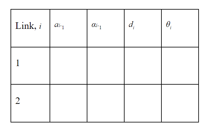
Figure 22 SAM-3 Smart Servo Motor
ai−1 = the distance from zi−1 to zi measured along xi−1 αi−1 = the angle between zi−1 to zi measured about xi−1 di is the distance from xi−1 to xi measured along zi θi is the angle between xi−1 to xi measured about zi
Step - 9: Form 0Tn =0T11T2 2T3....n−1Tn . This gives the position and orientation of the end-effector frame expressed in the base coordinates.
Related Posts
Check out my all posts-
December 1, 2019
How to Make A Teleoperated Robotic Hand? This is an approximately 50 cm lenght robotic hand, designed and produced ...
Category ROBOTIC DESIGN AND MODELLING
-
November 13, 2019
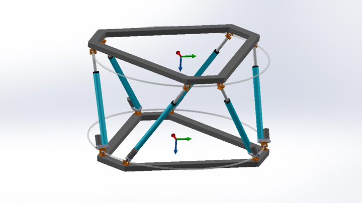
I prepared this post to explain how does inverse kinematics work with parallel robots.
Category ROBOTIC DESIGN AND MODELLING
-
May 6, 2016
The Game of Brains is a physical, competitive, and interactive game that participants play with their concentration leve...
Category DEVICE SOLUTIONS

Comments
11/3/2017
utku olcar
Control, Denavit Hartenberg, Forward Kinematics, Haptic, Humanoid, Kinect, Kinect Sensor, Kinematics, Microsoft, Real Steel, Remote Control, Robobuilder, Robot, Robot Balance, RQ-Huno, Skeletal Tracking, Smart Servo motor 3D Modelling, GUI Applications, Robotic Calculations, Robotic Design and Modelling
0 Comments